Off-Grid Solar Inverter 10KVA-120KVA Made In China High Intelligence
- Ref Price:
-

- Loading Port:
- China main port
- Payment Terms:
- TT or LC
- Min Order Qty:
- 1 pc
- Supply Capability:
- 1000 pc/month

- OKorder Service Pledge
- Quality Product
- Order Online Tracking
- Timely Delivery

- OKorder Financial Service
- Credit Rating
- Credit Services
- Credit Purchasing
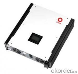
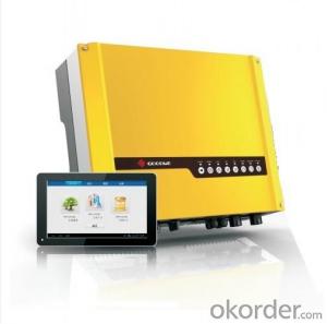
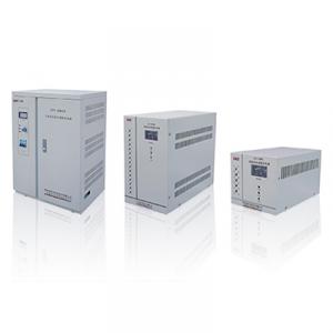
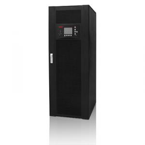
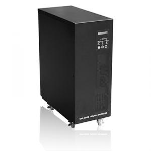
Off-Grid Solar Inverter 10KVA-120KVA
EA-GF series products use high speed DSP control unit, advanced high speed IGBT, MOSFET components, with pulse width modulation (SVPWM) technique disturbance type MPPT control, and double conversion system configuration. Under high-speed DSP system control, the system can quickly track panels to do high-power, load change and efficient multi-level control system, even if the mains input voltage and frequency suddenly change, over/under voltage, or power disturbances, it also can ensure provide the load with regulated voltage and frequency power. System has a reliable, environmentally friendly, high intelligence and other characteristics.
Villa, hotel, residential security, large base station, office, small manufacturing enterprises, computing centers, industrial automation equipment, network room, IDC data center, banking equipment, securities, health care, transportation, petrochemical and other solar systems.
● High reliability:
※ High-speed micro-controller DSP digital control technology to achieve real-time control, parameter setting, data detection, self-test function to ensure high reliable operation of the system.
※ With high speed switching characteristic, high voltage, high current, low internal resistance, low dissipation IGBT, MOSFET power components based, to ensure system security and reliability.
● N+1 modularized MPPT tracking system:
※ Multipath MPPT control system access, independent input, operation. More suitable for roof project, to improve power generation efficiency of the panels.
● PV proactive power supply function:
After detects PV energy, system will enter MPPT status automatically, and it will also adjust the power distribution, priority in the use of PV energy.
● Intelligent battery management system:
※ In this system, AC rectifier 、MPPT controller controlled by intelligent data exchange and communication system,user can set the battery capacity by themselves;battery configuration can be set by the operator interface,system will automatically
adjust the charging current ,charging voltage and charging mode.
※ In special cases,international technical engineer can adjust the charging rate and battery number according to the system configuration.
● Plenteous communication interface:
※ RS485、RS232 (standard),SNMP(Option).
※ Input dry contacts to switch on/off inverter, clear abnormal, EPO remotely. Output dry contacts singles for remote alarm.
● Intelligent storage staggering features:
System with intelligent peak load shifting function, the user can set the appropriate time period electricity according to the local electricity policy, to achieve load shifting features directly in order to bring economic value;
Model | 10KVA | 20KVA | 30KVA | 40KVA | 50KVA | 60KVA | 80KVA | 100KVA | 120KVA | |
Rated Power(KW) | 9KW | 18KW | 27KW | 36KW | 45KW | 54KW | 72KW | 90KW | 108KW | |
Rated Current (A) | 15A | 30A | 45A | 60A | 76A | 91A | 133A | 151A | 182A | |
Output Power Factor | 0.9 | |||||||||
Rated Input Voltage | 380V±20% | |||||||||
Rated Output Voltage | 380V±1% | |||||||||
Battery Voltage | 360Vdc | |||||||||
Battery Quantity | 30 units, 12V | |||||||||
Working Mode | PV、AC replenish | |||||||||
PV Input | Max Voltage | 750Vdc | ||||||||
Best Working Voltage(Vmp) | 444-550Vdc | |||||||||
Float Charging Voltage | 414V±1% | |||||||||
Max Efficiency | ≥98% | |||||||||
Equalize Charging Voltage | 428V±1% | |||||||||
Max Current | 40A | 60A | 120A | 180A | 240A | 300A | 360A | |||
PV Input Ways | 1+1(reserved) | 2+1(reserved) | 3+1(reserved) | 4+4(reserved) | 5+3(reserved) | 6+2(reserved) | ||||
MPPT Modular | 1+1(reserved) | 2+1(reserved) | 3+1(reserved) | 4+4(reserved) | 5+3(reserved) | 6+2(reserved) | ||||
AC Rectifier | Input Voltage Range | Three phases 380V ±20%(-10%~+20% can charge the battery) | ||||||||
Rated Frequency | 50 Hz / 60Hz(can be set backstage) | |||||||||
Frequency Range | 50Hz/60Hz±5Hz | |||||||||
Soft Start | 0-100% 10s | |||||||||
Power Factor | 0.8 | |||||||||
Float Charging Voltage(20℃) | 410V±1% | |||||||||
Max Voltage | 415V±1% | |||||||||
Max Charging Current(A) Battery Capacity Allowed | 12 | 25 | 38 | 50 | 62 | 75 | 80 | 100 | 120 | |
Inverter | Inverter Voltage | Three phases four lines +G 380Vac | ||||||||
Phase Voltage Setting | 220-230-240Vac(can be set backstage) | |||||||||
Output Voltage Accuracy | ±1% | |||||||||
Voltage Transients Range | ±5% | |||||||||
Transient Recovery Time | 20ms | |||||||||
Rated Frequency | 50Hz/60Hz±1% | |||||||||
Frequency Tracking Range | 50Hz/60Hz±3Hz | |||||||||
Crest Factor | 3:1 | |||||||||
Wave | Pure sine wave | |||||||||
THD | ≤3%(linear load) | |||||||||
Voltage Unbalance Degree | ±3%(100%unbalance load) | |||||||||
Overload | ≥105%-110%: transfer to bypass 1 hours later, recover when reduce load ≥110%-125%: transfer to bypass10 min later, recover when reduce load ≥125%-150%: transfer to bypass 1 min later, recover when reduce load ≥150%: transfer to bypass 10 s later, recover when user confirmed ≥200%: shutdown immediately, recover when user confirmed | |||||||||
Short Circuit | System current limited, shut down immediately, boot by user | |||||||||
Max Efficiency % | ≥90% | ≥91% | ≥92% | ≥92% | ≥93% | ≥93% | ≥93% | ≥93% | ≥93% | |
Bypass | Rated Voltage(V) | Three phases four lines+G 380Vac | ||||||||
Voltage Range | ±20% | |||||||||
Rated Frequency(Hz) | 50/60Hz±5Hz | |||||||||
Max Current | 19 | 38 | 57 | 76 | 95 | 114 | 122 | 152 | 182 | |
Battery Management | End of Discharge | 315VDC | ||||||||
Charging Current Setting | Factory setting is 0.15C10 ; user can set 0.05-0.3 C10 | |||||||||
Charging Current Setting | Equalizing charging and float charging automatically transfer, automatic temperature compensation for battery (when battery detection not connected, default environment temperature) | |||||||||
Staggering Depth of Discharge Settings | 1.85V-2.1V; can be set by user | |||||||||
Transfer Time | Inverter/Bypass Transfer Time | 0ms | ||||||||
Inverter/Bypass Transfer Time | 0ms | |||||||||
Communication Interface | Remote Control Input | Inverter on、off、abnormal clear、emergency power off | ||||||||
PC Monitoring Interface | RS232、RS485、SNMP (optional) | |||||||||
Dry Contact | Bypass input abnormal、rectifier input abnormal、system fault、system warning、 low battery、overload 、fans fault、generator ON/OFF | |||||||||
Environment | Operation Temperature | 0-42℃ | ||||||||
Max. Relative Humidity | 90% (non condensed) | |||||||||
Max. Working Altitude | 1000m (100 m higher, 1% derated; max 4000m) | |||||||||
Other | Cooling Way | Forced ventilation (Fans speed varies with the load) | ||||||||
Noise(1m varies with load and temperature )dB | 65 | |||||||||
Mean Time Between Failures(MTBF) | 200,000 hours | |||||||||
Defend Grade(EN60529) | IP20 | |||||||||
Power Line Input | Bottom | |||||||||
Standard | IEC62040-1-1、EN62109-1:2010, EN62109-2:2011 | |||||||||
Dimensions(WxDxH)mm | 600×700×1750 | 1000×800×1700 | ||||||||
Packing Dimensions(WxDxH)mm | 690×790 ×1850 | 1090×890 ×1800 | ||||||||
Weight | 250 | 280 | 300 | 320 | 345 | 360 | 400 | 420 | 445 | |
· Q. What is an UPS and What it is for ?
An uninterruptible power supply (UPS) is a device that allows your computer or telephone switch or critical equipement to keep running for at least a short time or longer time when the primary power source is lost. It also provides protection from power surges, spikes, brownouts, interference and other unwanted problems on the supported equipment.
· Q. How long the UPS to run when power goes?
This can take 3 paths.
1.You can pick a UPS that is rated for pretty much the full VA you need so it will be running at 100% of capability and will thus last 'n' minutes.
2.You can pick a UPS that is rated at a much higher VA value than you really need so, for example, is running at 50% of capability and will thus last for longer than the UPS from option 1.
3.You can use extra external battery packs to run for longer. If charging capability allows, the more and the bigger batteries you take with, the longer time UPS runs.
or using a generator after about 6 hours, it will be more cost-effective, with a short runtime UPS to bridge the generator start-up gap.


- Q:Three-phase photovoltaic inverter grid, the use of phase-locked loop is what?
- In addition to the function of converting DC current into alternating current, the inverter also has the maximum output tracking function (MPPT), overvoltage protection, short circuit protection, island protection, overheat protection, overload protection and DC grounding
- Q:What is the difference between a grid-connected inverter and an off-grid inverter? What are the advantages of a hybrid inverter?
- Grid-connected inverter does not need energy storage, but the energy can not be controlled, how much light to send online to the number of online, simply do not want people to the grid does not like.
- Q:The function of photovoltaic grid - connected inverter
- Finally, a sinusoidal AC output for a grid-connected photovoltaic power generation system is generated by a low-pass filter.
- Q:How the output voltage of the PV inverter and the grid-connected voltage are determined
- supply through the cable to the battery. The use of household appliances connected to the power converter output can be used in the car a variety of electrical appliances. The available electrical appliances are: mobile phones, laptops, digital cameras, cameras, lights, electric razors, CD players, game consoles, handheld computers, power tools, car refrigerators and various tourism, camping, medical emergency appliances Wait.
- Q:Grid-connected inverter is generally divided into photovoltaic power generation grid-connected inverter, wind power grid-connected inverter, power equipment and grid-connected inverter and other power generation equipment power generation inverter.
- Grid-connected inverter is generally used with large-scale photovoltaic power plant system, a lot of parallel PV string is connected to the same set of inverter DC input, the general power of the use of three-phase IGBT power module, power
- Q:What are the methods of photovoltaic grid-connected inverter control
- Sine wave output inverter control integrated circuits, sine wave output of the inverter, the control circuit can be used microprocessor control, such as INTEL company produced 80C196MC, Motorola produced MP16 and MI-CROCHIP company PIC16C73 and so on, these single-chip microcomputer has a multi-channel PWM generator,
- Q:What is the PV inverter starting voltage
- The inverter not only has the function of direct current conversion, but also has the function of maximizing the performance of the solar cell and the system fault protection function. (With grid system), automatic voltage adjustment function (for network connection), DC detection function (for network connection), DC grounding detection (for network connection), automatic power control function Function (for grid connection). Here is a brief introduction to automatic operation and shutdown function and maximum power tracking control function.
- Q:Is the PV inverter a current source or a voltage source?
- Photovoltaic inverter, also known as power regulator, according to the inverter in the use of photovoltaic power generation system can be divided into two kinds of independent power supply and grid.
- Q:Photovoltaic grid-connected inverter problem
- But Baidu Encyclopedia clearly pointed out: the zero line is the secondary side of the transformer leads the neutral point of the line, and the phase line constitutes a circuit for power supply equipment.
- Q:The working principle of photovoltaic grid - connected inverter
- Full-bridge inverter circuit to overcome the shortcomings of the push-pull circuit, the power transistor to adjust the output pulse width, the output AC voltage RMS that changes. Since the circuit has a freewheeling circuit, even if the inductive load, the output voltage waveform will not be distorted. The disadvantage of this circuit is that the upper and lower arms of the power transistor are not common, so you must use a special drive circuit or use isolated power supply. In addition, in order to prevent the upper and lower arm co-conduction, must be designed to turn off after the conduction circuit, that must be set dead time, the circuit structure is more complex.
1. Manufacturer Overview |
|
|---|---|
| Location | |
| Year Established | |
| Annual Output Value | |
| Main Markets | |
| Company Certifications | |
2. Manufacturer Certificates |
|
|---|---|
| a) Certification Name | |
| Range | |
| Reference | |
| Validity Period | |
3. Manufacturer Capability |
|
|---|---|
| a)Trade Capacity | |
| Nearest Port | |
| Export Percentage | |
| No.of Employees in Trade Department | |
| Language Spoken: | |
| b)Factory Information | |
| Factory Size: | |
| No. of Production Lines | |
| Contract Manufacturing | |
| Product Price Range | |
Send your message to us
Similar products
New products
Hot products
Hot Searches
Related keywords
You Might Also Like